Position Sensor: Integral or Remote?

Celso Nobre |
 |
Quite often, some criteria for projects or installation details must be revised after the industrial process starts running. Even if a project was thoroughly discussed, planned, revised and approved, it is practically impossible not to perform modifications on the field when mounting the instrumentation, or even after the start up of the plant.
In some cases, when the vibration on the process is too high and exceeds the limits, the mechanical parts of the device can wear out. Threads and connections may also deteriorate, in addition to bad contacts on terminals whose cables were not tightened adequately.
Other situations involve high temperatures near tanks and pipes whose thermal dissipation and cooling do not work as expected. Devices with intensive technological electronics do not stand well high temperatures, because, as they work constantly under severe conditions, their lifetime will be shorter and will need frequent care from the maintenance crew.
Eventually, we may need to get close to the devices to check their performance or even read the valve local position indicator. And similarly to the instrumentation, the human body cannot be exposed to excessive temperatures, since we may need to be near to piping that sometimes reach 100ºC or above.
Lastly, there may be the need to reach a valve entangled in the middle of a net of piping or equipments to check locally the conditions of the valve or the stem. The harder it is the access for the technician to check, the more difficult it will be for the work to be done.
When a control valve, for example, uses a positioner based in levers and mechanical connections to measure the valve position, it is difficult to find solutions that minimize the mentioned aspects.
This inconvenience does not happen, however, with positioners without mechanical contact that measure the valve stem position. This is true for SMAR´s Valve Positioners line.
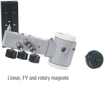
The SMAR FY301 Valve Positioner line (4 a 20 mA with Hart protocol), FY302 (Foundation protocol), FY303 (Profibus protocol) or still FY400 (4 a 20 mA with Hart protocol) use the magnetic sensor technology to measure the valve shaft position, both with linear and rotary motion.

The magnetic position sensor runs with oppositely polarized magnets generating an electric signal on the Hall Effect sensor. The magnets move during the valve opening and shutting, as they are mounted on their stems. When in motion, these magnets generated a tension on the Hall Effect sensor, one that is measured by the positioner electronic board.

Therefore, there is no mechanical contact between the positioner and the moving valve shaft.
Notice that the same Hall Effect measuring principle is used in the SMAR TP Line Position Transmitter, which is also presented in the several communication protocol versions.
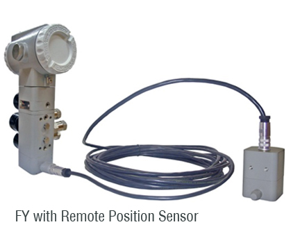
The fact that it does not have mechanical connections prompted the launch of the remote position sensor, both for Valve Positioners and Position Transmitters.
The difference is that the integral sensor is replaced by two sets of connectors and an extension cable. The cable receives the signal generated by the magnet on the Hall Effect sensor on the field to the Valve Positioner or the Position Transmitter.
The cables have standard lengths of 5, 10, 15 and 20 m.
The Valve Positioner and the Position Transmitter are also supplied as remote position sensors, when specified by the user. But the user himself can modify the “integral sensor” version to “remote sensor”, if necessary.
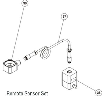
This modification is done with a small number of spare parts, as shown on the figure below.
 The figure beside may be found on our instruction manual pages. The spare parts are easily identified on the exploded view of the product. The following manual pages list down the available spares and their purchasing codes.
The integral sensor is substituted by the remote sensor set (part n. 36) that includes the connector for the extension cable. The remote extension set (part n. 38) will be attached to the valve, with the same mounting support used before on the positioner. The positioner, which was mounted on the valve, can now be installed at a maximum distance of 20 m, by using an “L” profile support, supplied by SMAR with an “U” clamp for mounting on a 2” pipe.
March 2011


