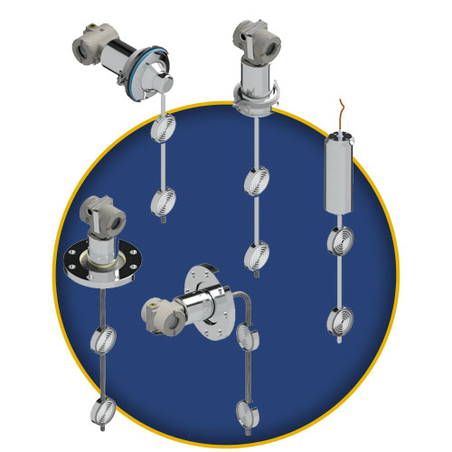
DT300Series
Density Transmitters - Specifications

Functional Specifications
|
Output and Communication Protocol
|
HART®: Two-wire, 4-20 mA with super-imposed digital communication (HART® Protocol).
Foundation fieldbusTM e PROFIBUS PA: Digital only. Complies with IEC 61158-2:2000 (H1): 31.25 kbit/s voltage mode, bus powered. |
|
Power Supply/Current Consumption
|
HART®: 12-45 Vdc.
Foundation fieldbusTM e PROFIBUS PA: Bus powered: 9 to 32 Vdc. Quiescent current consumption: 12 mA. |
|
Indicator
|
4½-digit numerical and 5-character alphanumerical LCD indicator (optional).
|
|
Hazardous Area Certifications
|
HART®, Foundation fieldbusTM e PROFIBUS PA: Explosion proof, weather proof, intrinsically safe, CEPEL, Dekra/EXAM, FM, NEMKO and NEPSI.
Foundation fieldbusTM e PROFIBUS PA: FISCO Ex ia IIC T4 (CEPEL, Dekra/EXAM, NEPSI) and FNICO Ex nl IIC T4 (CEPEL, Dekra/EXAM) |
|
Other Certification
|
HART®, Foundation fieldbusTM e PROFIBUS PA:3A Sanitary Standard.
|
|
Zero and Span Adjustments
|
Noninteractive, via digital communication or local adjustment.
|
|
Failure Alarm (Diagnostics)
|
Detailed diagnostics through communication for all protocols.
HART®:In case of sensor or circuit failure, the self diagnostics drives the output to 3.6 or 21.0 mA, according to the user’s choice.
Foundation fieldbusTM: For sensor circuit failures, events are generated and status is sent to link outputs. Detailed diagnostics are available in the contained parameters. PROFIBUS PA: For sensor or circuit failures, status is sent to output parameters. Detailed diagnostics are available in the contained parameters. |
|
Temperature Limits
|
Ambient: -40 to 85 °C (-40 to 185 °F)
Process: -20 to 150 °C (-04 to 302 °F) Storage: -40 to 100 °C (-40 to 212 °F) Digital Display: -10 to 60 °C (14 to 140 °F) |
|
Turn-on Time
|
HART®: Performs within specifications in less than 5 seconds after power is applied to the transmitter.
Foundation fieldbusTM e PROFIBUS PA: Performs within specifications in less than 10 seconds after power is applied to the transmitter. |
|
Configuration
|
HART®: By digital communication (HART® protocol) using the configuration software CONF401, DDCON (for windows), HPC301 or HPC401 (for Palms). It can also be configured using DD and FDT/DTM tools.
Foundation fieldbusTM e PROFIBUS PA: Basic configuration may be done using the local adjustment magnetic tool if device is fitted with display. Complete configuration is possible using configuration tools. |
|
Static Pressure Limit
|
7 MPa (70 kgf/cm²) (1015 psi).
|
|
Humidity Limits
|
0 to 100% RH.
|
|
Damping Adjustment
|
0 to 32 seconds in addition to intrinsic sensor response time (0.2 s) via digital communication.
|
Performance Specifications:
|
Electrical Connection
|
1/2 - 14 NPT
M20 X 1.5 PG 13.5 DIN |
| Process Connection | Industrial Model: 316 SST Flange ANSI B16.5 4”. Sanitary Model: 304 SST Tri-clamp 4”. |
| Wetted Parts | Isolating Diaphragms: 316L SST or Hastelloy C276. Wetted O-Rings (For Sanitary Model): Buna N, Viton™ or Teflon™. |
| Nonwetted Parts | Electronic Housing: Injected aluminum with polyester painting or 316 SST. Complies with NEMA 4X, IP66/68 W. Fill Fluid: Silicone (DC200/20, DC704), Glycerin and Water, Neobee M20 Propylene Glycol. Cover O-Rings: Buna N. Identification Plate: Aço Inox 316. |
| Mounting | Side or top mounted. |
| Approximate Weights | 8 kg (18 lb) – Sanitary Model. 13 kg (26 lb) – Industrial Model. |
Physical Specifications
|
Reference Conditions
|
Temperature of 25 °C (77 °F), atmospheric pressure, power supply of 24 Vdc, silicone oil fill fluid, isolating diaphragms in 316L SST and digital trim equal to lower and upper range values.
|
| Accuracy | For range 1: ±0,0004 g/cm³ (±0,1 °Bx) For range 2: ±0,0007 g/cm³ Linearity, hysteresis and repeatability effects are included. |
| Stability (for 12 months) | For range 1: 0,021 x 10-³ g/cm³ For range 2: 0,083 x 10-³ g/cm³ |
| Ambient Temperature Effect (per 10 °C) | For range 1: 0,003 x 10-³ g/cm³ For range 2: 0,013 x 10-³ g/cm³ |
| Static Pressure Effect | Pressão Estática no ZeroZero Static Pressure For range 1: 0,001 x 10-³ g/cm³ For range 2: 0,004 x 10-³ g/cm³ |
| Power Supply Effect | ± 0.005% of calibrated span per volt.. |
| Mounting Position Effect | It can be eliminated after installation. No span effect. |
| Electro-Magnetic Interference Effect | Designed to comply with IEC 61326-1, IEC 61326-2-3, IEC 61000-6-4 e IEC 61000-6-2. |


